Cos-phi compensation - White paper
What is Cos Phi?
What does Cos Phi mean? Cos Phi indicates how much power is lost during the 'transport' of power. The ratio of actual power to apparent power is Cos Phi. The current is out of phase with respect to the voltage. This causes reactive power.
Reducing reactive power
In addition to actual power, cables, lines and transformers must also transport reactive power. Reactive power is the loss of energy. If you want to use the infrastructure more efficiently or are at the limit of your connection capacity, it is interesting to reduce your reactive power so that you can still "grow" without expanding your installation. You may also have to pay your grid operator extra for the transported reactive power.

What is reactive power?
Active and reactive energy
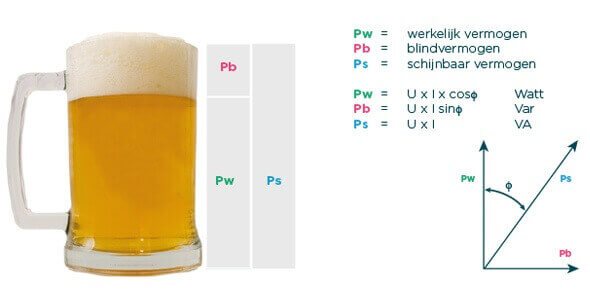
The purpose of the electricity grid is to transport energy from the source to the consumer. The energy consists of active energy (Pw) and reactive energy (Pb). Active energy is converted into mechanical energy (motor), light (lamp) or thermal energy (heat or cooling). Reactive energy is used to maintain the magnetism of transformers, ballasts and gas discharge lamps. As a result, current and voltage are not in phase.
Phase shift - Tracking of current
In an inductive load, the current "jumps" on the voltage. The degree to which the current rushes in response to the voltage is indicated by phi, or the letter Φ. Phi is the angle between voltage and current. In addition to phase shift, in some cases reactive power can also be caused by mains pollution (harmonics).

Phase shift voltage-current cos phi
Sensible energy
The figure below shows that only active energy, the actual power, is meaningful (the beer). The reactive power is not converted into meaningful energy (the foam). If we add up the beer and the foam, we get the minimum size of the glass. In energy technology, if we add up the actual power and the reactive power, we get the minimum required capacity of the electrical infrastructure. The more reactive power, the more copper, transformer and connection capacity is required.

Blinding power compensation
Working factor cosΦ
The ratio of real power to apparent power is the power factor or cosine phi (cosΦ). Cos Phi can be improved with Cos Phi Compensation. Cos Phi is calculated as follows:
Workingfactor = Pw / Ps = cosΦ (bij 50 Hz)
Reactive power generated by harmonics
The increase in electronic loads such as frequency converters, electronic power supplies and LED lighting causes more and more harmonic contamination. Harmonic pollution causes additional reactive power.
What is harmonic?
A harmonic is a frequency that is an integer multiple of the fundamental frequency. The fundamental frequency is the lowest (natural) frequency that a system naturally exhibits. An eigenfrequency of a system is a frequency that the system can naturally exhibit. Read more about higher harmonics.
Active filter
The ratio of real to apparent power at all frequency components is the power factor. If higher harmonics in the voltage network cause problems or increase the apparent power, it is best to use an active filter. We explain this in more detail in our White Paper on active filters We will tell you more about this. The power factor is calculated as follows:
Powerfactor = Pw / Ps (at all frequency components)
Consequences of a poor Cos-Phi
- Overloading and overheating of the electrical installation.
- Higher connection value with the grid operator than necessary.
- Percentage load per room, rack or circuit.
- Unintentional switching off of installation circuit breakers and therefore processes.
- A fine from the energy company and a higher energy bill than necessary.
- A high energy bill.
Cos Phi compensation - Reducing reactive current
Improving the cos-phi, or reducing the reactive current, soon makes sense. In addition, compensating the cos-phi has a number of positive side-effects:
- Compensation for minor interruptions and transients, which increases reliability.
- More optimal use of connection capacity.
- Compensation of varying loads.
- Filtering of harmonics (up to 5th and 7th, above active filtering).
- Strong reduction of CO² emissions.
Where to compensate for blind current?
Load compensation
Decentralised compensation (i.e. installation of the cos-phi compensation at the load) is generally recommended for consumers with an individual load of more than 25 kW that are almost always in operation, such as large fans, hammer mills and transformers with a relatively stable load.
Compensation at the main distributor
Centralised compensation (i.e. installation of the compensation at the main distributor) is recommended where the load varies. An automatically controlled compensation bank is almost always chosen in such cases.

Decentralised versus centralised cos-phi compensation
Types of compensation banks Cos Phi compensation
In standard situations, we always recommend using tuned compensation banks for Cos Phi compensation. These compensation banks filter out harmonics and protect the TF signal of the power company from short circuits.
1. Non-regulated, tuned compensation bank (with coils)
An unregulated, tuned compensation bank is often used for motors with a relatively high power and mains transformers with a relatively stable load.
2. Regulated compensating bank with tuning
We recommend a regulated compensation bank with adjustment for situations where compensation is centralised and the load can vary. The capacity of a regulated compensation bank is matched exactly to the amount of compensation capacity required, using the Janitza Prophi controller. In this way, overcompensation is prevented and the set is universally applicable.
3. The thyristor-controlled compensation bank with tuning
The thyristor-controlled compensation banks are used in situations where the load changes quickly, such as welding lines, lift systems, cranes and injection moulding machines. The thyristors switch quickly and precisely on the zero crossing of the current. This means that the load is monitored quickly and precisely, preventing under- or over-compensation.


Seven questions for cos phi compensation
With cos-phi compensation, you can save a lot of costs. Incorrect application of this compensation can lead to problems such as over- or under-compensation, problems with the power company or overload, damage or even fire. This is why we provide you with good advice, in which the following questions are important:
1. In which environment is the Cos-Phi compensation applied?
- Industry
- Office
- Clean process industry
2. Is there room to put the compensation away?
- The physical space for placing the compensation.
- Moisture and dirt are bad for the compensation.
- The room must not become too hot.
3. Is there room on the distributor to connect the compensation?
- Three phases and one earth are required to connect the compensation.
- Consider the correct application of fuse ratings and cable cross sections of the compensation.
4. What kind of transformer should be used for compensation?
- How many kVA is the transformer?
- What is the short-circuit voltage of the transformer (in % on the type plate)?
- Are there any transformers in parallel?
5. What kind of load is there on the installation to be compensated?
- Rapidly changing loads? (spot welding machine, crane), then thyristor-controlled compensation.
- Is there a lot of mains pollution? (frequency regulators, switching power supply, etc. welding equipment)
6. What is the frequency of the present tone frequency signal?
- How many Hz is the TF signal? Your network operator knows the answer to this.
7. Is the controller easy to connect?
- One current transformer is required for the Janitza controller. Can this be used?
- Can the current transformer be short-circuited?
- Is there a safe measuring voltage?
Table - Fuse ratings and cable cross-sections
PFC Cable diameter, fuse rating (for 400V/50Hz) nets
| Power in kvar | Rated current in A | Cablediameter & NYY-J mm² | HRC fuse value |
| 5 | 7 | 4x 2,5 | 16 |
| 7,5 | 10 | 4x 4 | 20 |
| 10 | 14 | 4x 4 | 25 |
| 12,5 | 18 | 4x 6 | 35 |
| 15 | 22 | 4x 6 | 35 |
| 17,5 | 25 | 4x 10 | 50 |
| 20 | 29 | 4x 10 | 50 |
| 25 | 36 | 4x 16 | 63 |
| 30 | 43 | 4x 16 | 80 |
| 37,5 | 54 | 4x 25 | 100 |
| 50 | 72 | 3x 35/16 | 125 |
| 55-65 | 79-94 | 3x 35/16 | 160 |
| 70-85 | 101-123 | 3x 70/35 | 200 |
| 86-100 | 124-145 | 3x 95/50 | 250 |
| 101-125 | 146-181 | 3x 120/70 | 250 |
| 126-160 | 182-231 | 2x 3x 70/35 | 315 |
| 161-180 | 233-260 | 2x 3x 95/50 | 400 |
| 181-200 | 261-289 | 2x 3x 120/70 | 400 |
| 201-250 | 290-361 | 2x 3x 150/70 | 500 |
| 251-300 | 362-434 | 2x 3x 185/95 | 600 |
|
Cable diameters only suitable for the capacitor capacities specified |
|||
Read more white papers
Read more about specific substructures in one of the white papers below. On the corresponding page, you can request the white paper free of charge as a PDF.
- Voltage dips and current dips
- Active dynamic filtering
- Measurement accuracy and measurement uncertainty
- Higher harmonics and pollution
- Blindstroom reduceren en compenseren
- Power quality of electrical energy
