Higher harmonics - What is it? - Insight into higher harmonics
What are harmonics? A harmonic is a frequency that is an integer multiple of the fundamental frequency. The fundamental frequency is the lowest (natural) frequency that a system naturally exhibits. An own frequency of a system is a frequency that, that system naturally exhibits.
Harmonic distortion
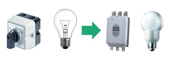
Due to the increase in electronic equipment, the network is becoming increasingly polluted. Star-triangle switches are replaced by electronic drives, incandescent lamps are replaced by LED lamps. We all have PCs and flat-screen TVs in-house. This creates higher harmonics and harmonic distortion.
Overloading and inexplicable tripping
The grid is generally strong enough to cope with these problems, but they can still lead to problems locally. Overloading cables and the inexplicable tripping of machines are well-known examples.


What are higher harmonics?
Normally the mains voltage is pure and perfect sinus formation. If a linear load is connected to this, the current is purely sinusoidal. If the sine is distorted, it can be described as the sum of several sinuses with a frequency that is equal to a multiple of the fundamental frequency (50 Hz).
Fourier analysis
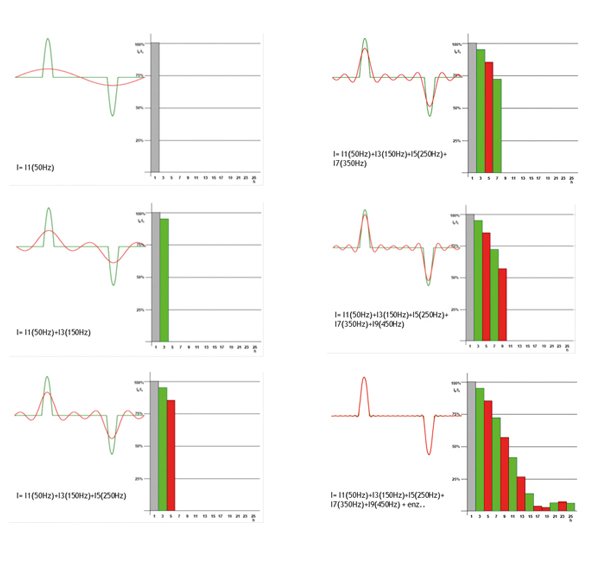
We call this description (or analysis) of the signal the fourier analysis. This is illustrated in Figure 2 (page 5 - PDF white paper). The current that we see here (green) is a current that is absorbed by an electronic power supply. We can describe this current as the sum of individual sinusoidal components (red).
We can display the individual sinusoidal components with bars. The x-axis shows the frequency of the harmonic components in multiples of the fundamental frequency. The y-axis shows the percentage values of the amplitude in relation to the fundamental wave. Unravelling a non-sinusoidal current into individual sinusoidal components with different frequencies, shown in a bar graph, is also called the fourier analysis.
The amplitude of a (periodic) vibration is the largest deviation from the equilibrium position, or, in other words, the maximum result."
The green waveform that we see is made up of:
- A fundamental wave with a frequency of 50 Hz, amplitude = 100%
- A 3rd harmonic f = 150 Hz with an amplitude of 95% with respect to the fundamental wave
- A 5th harmonic f = 250 Hz with an amplitude of 85% relative to the fundamental waves and 7th harmonic f = 350 Hz with an amplitude of 70% relative to the fundamental wave
- A 9th harmonic 7 = 450 Hz with an amplitude of 60% with respect to the fundamental wave
We have now approximated the pulsed current shape of the sine. To top it off, you see the fourier analysis up to the 25th harmonic at the bottom right of the figure.
In formula form:
IRMS = √ I1 (50Hz) 2 + 95% * I1 (150Hz) 2 + 85% * I1 (250Hz) 2 + 70% * I1 (350Hz) 2 + 60% * I1 (450Hz) 2 + etc.
The total harmonic distortion (THD) is the sum of all harmonic components of the voltage or current set against the ground harmonic of voltage or current. The THD is indicated in percentages. The higher the percentage, the more harmonic pollution.
Sub and inter harmonics
Sub-harmonics are harmonics with a frequency lower than the fundamental harmonic (50 Hz) but unequal to a multiple of the fundamental harmonic.
Harmonics and reactive power
Reactive power is used to maintain the magnetism of transformers, control gear and motors. Current and voltage are then not in phase. The figure below makes it clear that only active energy, the actual capacity, makes sense (the beer). The reactive power (the foam) is not converted into meaningful energy. When we add the beer and the foam together, we get the minimum size of the glass, which we can consider as the required apparent power. The more reactive power, the more copper transformer and connection capacity required. This theory only applies with a pure sine wave shape of 50 Hz, so with linear loads.
Non-linear load
With non-linear loads we must deal with higher harmonics. Also, the current and voltage of higher harmonic components are not in phase with each other. This also generates reactive power.
The reactive power that is generated by the phase shift between voltage and current at 50 Hz is called phase shifting or fundamental reactive power. We call the reactive power generated by the higher harmonic component's, distortion reactive power. The total reactive power is thus obtained by adding the phase shifting reactive power and the distortion reactive power vectorially.
Now the Cos Phi is the ratio between the actual and the apparent power at 50 Hz. The power factor is the ratio between the actual and apparent power at all frequency components.
Cos Phi = Pw / Ps (50Hz)
Power factor (power factor) = Pw / Ps (for all frequency components)

Impact of higher harmonics
Higher harmonics therefore generate extra reactive power, but what are the real consequences of higher harmonics?
Overloading of the neutral conductor
If many switching power supplies or lamps with electronic control gear are included in a 3-phase network with zero, then the proportion of 3rd harmonic components in the current is large. A property of the 50 Hz ground harmonic is that the vector sum of the current of the 3 phases is zero at any time. With an equally loaded system, no current flows through the zero. The 3rd harmonic components are shifted by 120 °, but they still add. That is why they add themselves to the zero, so that the current through the zero is much larger than expected.
If the phase current of the fundamental wave is 10 A, and the proportion of 3rd harmonic current is 60%, then the zero runs through 18 A. The above theory also applies to the harmonic components that are a multiple of 3, so also the 9th, 15th, 21st and so on.

Harmonics with a multiple of three are eliminated by the zero in TN systems
The unexpected switching of security devices
Higher harmonic currents can lead to the unexpected switching of safety devices. Safety devices are often calculated by adding together the actual capacity of the individual taxes. However, harmonics cause distortion reactive power. This reactive power results in additional melting of the melting wires and bimetals, so that switching off takes place earlier than one would expect based on the calculated actual power.
The capacitive effect of an installation in combination with higher harmonics ensures greater leakage currents. As a result, the earth leakage switches can switch on earlier than we expect.
Overloading of cables in an electrical infrastructure
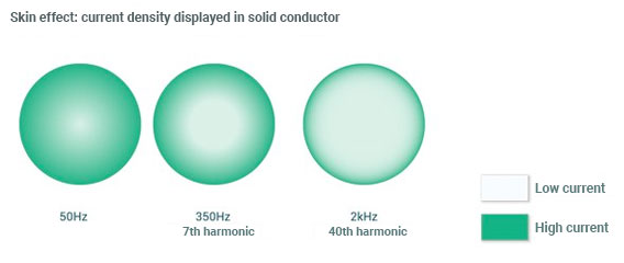
Harmonics provide extra reactive power. This reactive power is responsible for heat development in cables. In addition, the "skin effect" ensures that streams of components of higher frequencies run more on the outside of the conductor, creating extra heat.
Overloading transformers
Harmonic currents will increase the copper, eddy current and leakage current losses, creating extra heat. The skin effect also provides extra warming. The efficiency of a transformer decreases due to the extra heat development. This increases the k factor of a transformer, so that the maximum load must be reduced. This is also called the "de-rats" of a transformer. If a k factor is 1.15, the transformer may only be loaded for 85% of the nominal power.
Overload of capacitors
With a polluted mains voltage, the current through a capacitor can rise considerably. This is because the resistance (impedance) of a capacitor is inversely proportional to the frequency: Zc = 1 / 2πfC
Extra heating of engines
If the mains voltage is polluted, additional eddy current losses are generated in an electric motor. In addition, higher harmonic voltages ensure that fields are worked up that want the motor to run at a different speed or opposite.
Resonance
If capacitive and inductions are present in the network, such as when applying for reactive current compensation, resonance can occur. Resonance occurs at those points where the impedance of a circuit connected in series is minimal (when injecting a current) and the impedance of a parallel circuit is maximum (when injecting a voltage).
'Resonance is a physical phenomenon that occurs with vibrations. A vibrating object can make another object vibrate because the vibrations are transmitted via an intermediate substance.'

Solving problems due to harmonics
In many cases, the consequences of harmonic problems can be properly controlled by continuously monitoring the harmonics and introducing minor adjustments to the design of the installation. Sometimes the costs of adjusting the installation are so high that (active) filters must be applied. Read more about active dynamic filters.
Installation design
When selecting the line cross-section, transformers and protection devices, consider the presence of, for example, 3rd harmonic current components. We do not limit the flows, but opt for "overcapacity" in the installation such as thicker pipes.
Consider when distributing different taxes among different groups. Equipment that is sensitive to harmonics should be separated as much as possible from equipment that generates many harmonics.
Connect large polluting devices as close as possible to the transformer. Here the grid is the strongest and the adverse effects of the polluting devices on the quality of the voltage for the other devices are limited as much as possible.
Passive filters
Passive filters can be used to block specific harmonic currents (blocking filter) or to form a low impedance for these harmonic currents (suction filter). A blocking filter can cause higher harmonic voltages and is expensive because the total power must be passed through the filter. A suction filter can have the disadvantage that it can also suck in harmonic currents from "the neighbors". This can overload the filter. Because the nets start to behave dynamically, the passive filters are becoming increasingly unclear and active filters are being applied.

A suction filter for various harmonic current components
Active filters
An active filter can be compared to an 'anti-noise' installation. An active filter continuously measures the shape of the current and, based on this measurement, offers a counter current for the polluting current components. The result is that an almost sinusoidal current is created after the filter.
Because an active filter is a freely programmable power source that can be used in any type of installation. With the help of setting the parameters, it is possible to choose on which type of contamination the filter must concentrate and to what extent it must eliminate it. This means that filters are not only used to eliminate higher harmonics, but also for resonances, flicker, imbalance and a bad cosine phi.
More information? Read the white paper "Active Dynamic Filtering"
Harmonics and standards
The standards below are voltage quality standards and describe the maximum harmonic voltage pollution in public and non-public networks.
EN50150 Voltage quality standard for public networks for low and medium voltage
This standard describes the minimum requirements that the quality of the grid voltage must meet at the transmission point from the grid manager to the customer. The EN50160 is part of the network code. The EN50160 describes among other things the maximum harmonic voltage pollution up to the 25th order.
EN61000-2-4 Voltage quality standard for non-public industrial networks up to 35kV
This standard describes the minimum requirements that the quality of the mains voltage must meet in the non-public (private) domain. This standard describes, among other things, the maximum harmonic pollution up to the 50th order and also provides recommendations for interharmonics and harmonics up to 9 kHz. The person responsible for the installation is responsible for ensuring that the voltage quality meets this standard.
EN61000-2-2 Voltage quality standard for public low-voltage networks
This standard largely corresponds to EN50160 but describes the maximum harmonic voltage pollution up to the 40th order.
More information: Read the white paper "Power quality"
Emission standards power pollution
With the Power Quality Analyzers UMG 605-PRO and UMG 512-PRO from Janitza you can print complete reports in accordance with EN50160 and EN61000-2-4. This makes it possible to see at a glance whether the harmonic pollution is within the permitted limits.
The standards below are emission standards (current quality standards) and describe the maximum harmonic current pollution that appliances can emit in the network.
Emission standards for electricity pollution in the network at the device level
| EN61800-3 | Maximum harmonic "power pollution" of frequency converters |
| EN61000-3-2 | Maximum harmonic "power pollution" of devices up to and including 16 A |
| EN61000-3-12 | Maximum harmonic "power pollution" of devices larger than 16 A and less than 75 A |
There are no standards yet for maximum power pollution at the level of connection with the network operator. This is also not that easy because voltage and current always influence each other. Poor voltage quality automatically leads to poor power quality and vice versa.
With the free Software GridVis supplied, it is possible to do extensive analyses and run reports according to current standards.
Measuring higher harmonics
KWh meters do not register higher harmonics. The blind consumption generated by harmonics is therefore not recorded by these meters. A standard energy meter (multimeter) is therefore not suitable for measuring signals with high frequencies. The range runs to a few kilohertz at most. True-RMS meters have a slightly higher range.
Power analysers
We use power analysers to properly measure higher harmonics. With power analysers from Janitza we can measure all individual harmonic components for all phases separately. With most models we also have the possibility to measure the harmonic components of the real and blind power. This makes it possible to determine the direction of the power of all individual harmonic components
Tabel 1 | Janitza meters with the extended measurement functions for higher harmonics |
|||||||||||||
| Janitza model | orde | equally harmonious | odd harmonics | interharmonic | power | voltage | actual power (+/-) | reactive power (+/-) | L1 | L2 | L3 | L4 | |
| UMG103 | Harmonics | 1-25e | x | x | x | x | x | x | x | ||||
| THD-U in % | x | x | x | ||||||||||
| THD-I in % | |||||||||||||
| UMG96RM | Harmonics | 1-40e | x | x | x | x | x | x | x | ||||
| THD-U in % | x | x | x | ||||||||||
| THD-U in % | x | x | x | ||||||||||
| UMG104/604-PRO | Harmonics | 1-40e | x | x | x | x | x | x | x | x | x | x | |
| THD-U in % | x | x | x | x | |||||||||
| THD-U in % | x | x | x | x | |||||||||
| UMG605-PRO | Harmonics | 1-63e | x | x | x | x | x | x | x | x | x | x | |
| THD-U in % | x | x | x | x | |||||||||
| THD-U in % | x | x | x | x | |||||||||
| UMG508/509-PRO | Harmonics | 1-40e | x | x | x | x | x | x | x | x | x | x | |
| THD-U in % | x | x | x | x | |||||||||
| THD-U in % | x | x | x | x | |||||||||
| UMG511/512-PRO | Harmonics | 1-63e | x | x | x | x | x | x | x | x | x | x | x |
| THD-U in % | x | x | x | x | |||||||||
| THD-U in % | x | x | x | x | |||||||||
Current measuring transformers have a good transmission characteristic of up to 2 kHz. This means that harmonic current components up to the 40th order can be accurately measured with the "classical" current transformers. Read more about current transformers.
Registering and monitoring harmonics
Most power analysers are equipped with (internal) memory. Important power quality parameters are monitored and stored in the memory. This makes it possible to do a harmonic analysis at any time of the day, but also to request a historical trend.
The Fourier analysis of an LED lamp

Historical values of the 3rd harmonic current
With the graphic programming language Jasic, it is possible to perform various actions depending on the size of the individual harmonic components.